1 Scope
1.1 This European Standard applies to the grades of stainless steels listed in Table 1, which are usually used in the cold drawn condition in the form of wire of circular cross-section up to 10,00 mm in diameter, for the production of springs and spring parts that are exposed to corrosive effects and sometimes to slightly increased temperatures (see A.1).
1.2 In addition to the steels listed in Table 1 certain of the steel grades covered by EN 10088-3 e.g. 1.4571, 1.4539, 1.4028 are also used for springs, although to much lesser extent. In these cases the mechanical properties (tensile strength, etc.) should be agreed between purchaser and supplier. Similarly, diameters between 10,00 mm and 15,00 mm may be ordered according to this standard; in this case the parties should agree upon the required mechanical characteristics.
1.3 In addition to this European Standard the general technical delivery requirements of EN 10021 are applicable.
2 Normative references
The following referenced documents are indispensable for the application of this document. For dated references, only the edition cited applies. For undated references, the latest edition of the referenced document (including any amendments) applies.
EN 10021, General technical delivery conditions for steel products
EN 10027-1:2005, Designation systems for steels一Part 1: Stee/ names
EN 10027-2:1992, Designation systems for steels – Part 2: Numerical system
EN 10088-3, Stainless steels 一Part 3: Technical delivery conditions for semi-finished products, bars, rods and sections for general purposes
EN 10204:2004, Metallic products . – Types of inspection documents
EN 10218-1, Stee/ wire and wire products一General- Part 1: Test methods
EN 10218-2, Steel wire and wire products – General – Part 2: Wire dimensions and tolerances CEN/TR 10261, lron and stee/一Review of available methods of chemical analysis
EN ISO 377, Steel and steel products – Location and preparation of samples and test pieces for mechanical testing (ISO 377:1997)
EN ISO 6892-1, Metallic materials一Tensile testing – – Part 1: Method of test at room temperature (ISO 6892-1:2009)
EN ISO 14284, Steel and iron一Sampling and preparation of samples for the determination of chemical composition (ISO 14284:1996)
3 Information to be supplied by the purchaser
The purchaser shall clearly state in his enquiry or order the product and following information:
a) the desired quantity;
b) the term spring steel wire or straightened and cut lengths;
c) the number of this European Standard: EN 10270-3;
d) the steel grade (see Table 1) and for grade 1.4301, 1.4310 and 1.4462 also the tensile strength level (see Table 2);
2) the nominal wire diameter (see Table 4) and for cut length the length and the length tolerance class (see Table 6);
f) the surface finish (see 4.3, i.e. coating);
g) the form of delivery (see 4.2);
h) the type of inspection document to be supplied (see 5.1);
i) any particular agreement made.
EXAMPLE
2 t stainless steel spring wire according to this standard, grade 1 .4310, normal tensile strength level and
nominal diameter 2,50 mm, nickel coated in coils with inspection document 3.1 according to EN 10204:2004:
2 t spring steel wire EN 10270-3 – 1.4310-NS – 2,50 – Ni-coated in coils, EN 10204:2004 – 3.1
4 Requirements
4.1 Manufacturing process
Unless otherwise agreed in the order, the manufacturing process used in the making of the stainless steel wire is left to the discretion of the manufacturer. The starting condition (+AT: solution annealed) of the wire (rod) is specified in EN 10088-3.
4.2 Form of delivery
The wire shall be supplied in coils, on spools, on spoolless cores or carriers. Several coils may be assembled on a carrier. Unless otherwise specified the form of delivery shall be at the manufacturer’s discretion. They shall however inform the purchaser about the form of delivery.
The delivery requirements are specified in 4.7.
Wire in straight lengths is normally supplied in bundles.
4.3 Surface finish
The wire may be coated or not. The specific coating and finish for stainless steel spring wire shall be agreedupon at the time of enquiry and order – e.g. uncoated, polished finish, nickel coated.
4.4 Chemical composition
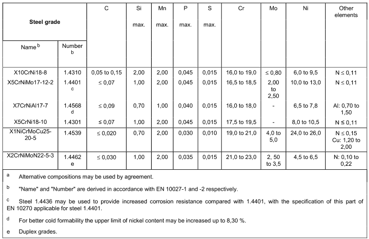
4.4.1 The requirements for the chemical composition given in Table 1 apply to the heat analysis.
4.4.2.The permissible deviation of the product analysis from the values specified in Table 1 shall be in accordance with the provision in EN 10088-3. For a single heat the deviation of an element in the product analysis may be only below the minimum or only above the maximum value of the range specified for the heat analvsic hut nnt hoth at the came time.
Table 1一- Chemical composition一Heat analysisa (% by mass)
4.5 Mechanical properties
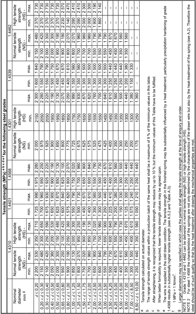
4.5.1 For the tensile strength in the as drawn condition the data of Table 2 shall apply.
Table 2- Tensile strength in the drawn condition
4.5.2 In addition to the requirements of Table 2 the maximum tensile strength range within one unit package (individual coil, spool or reel,.) shall satisfy Table 3.
For straightened and cut lengths the values of Table 3 apply for the individual bundles.
Table 3 – Tensile strength range within an individual unit package (coil/spool/bundle)

4.6 Technological properties
4.6.1 Coiling test
For evaluation of uniformity of coiling and surface condition the coiling test may be applied to wire with a
diameter of 0,50 mm to 1,50 mm. The spring coiled in accordance with 5.4.3 shall show a defect free surface condition without splits or fracture; the coil shall have uniform pitch of the turns and a fair dimensional regularity of its diameter.
NOTE
Although the usefulness of the coiling test is not generally recognized, it has been retained since it offers the possibility of revealing internal stresses. If doubtful test results are obtained the wire concerned should not be rejected immediately but efforts should be made by the parties concemed to elucidate the cause.
4.6.2 Wrapping test
The wrapping test may be applied to wire with a diameter of 0,30 mm to 3,00 mm. The wire shall not show any sign of cracks or surface imperfections when closely wrapped eight turns around a mandrel of a diameter equal to the wire size (see also 5.4.4).
4.6.3 Simple bend test
Where requested, the bend test may be applied for wire with a diameter over 3,00 mm. The wire shall withstand the test without any sign of failure.
NOTE
In some applications the material is severely deformed by bending. Such is the case for extension springs with tight hooks, springs with bends on legs, spring wire forms, etc. In such cases the bend test provides for a wire test very close to actual use.
4.7 Supply conditions of wire on coils/reels and spools
4.7.1 General
The wire of each coil shall consist of one single length of wire originating from only one heat. It shall be wound so that there are no kinks.
Where wire is delivered on spools, spoolless cores or carriers up to 10 % of those may consist of a maximum of two wire lengths. The joints shall be properly made, suitably marked and labelled.
4.7.2 Coil size
The internal diameter of unit packages (coil/reels or spools) shall reach at least the values given in Table 4, unless otherwise agreed.
Table 4- Wire diameter and associated minimum coil internal diameter

4.7.3 Circular wire cast
The wire shall be uniformly cast and take a circular cast. Unless otherwise specified the wap diameter of the wire supplied in coils/reels may expand when the binding wires are removed, but should usually not retract to less than the unit internal diameter, other than by agreement between supplier and purchaser. The expansion shall be approximately even within a single unit package and within all the units in a production batch.
4.7.4 Helix cast of wire
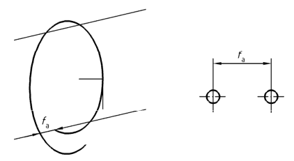
The wire shall be dead cast, free from helix cast. The requirement shall be considered fufilled in the case of wire below 5,00 mm if the following condition is satisfied.
An individual wap taken from a unit package and freely hung on a hook may show an axial displacement’ fa’ at the ends of the wap (see Figure 1); the displacement fg shall not exceed a value given by the following equation:

where
fa the axial displacement in mm;
W the diameter of the free wap in mm;
d the diameter of the wire in mm.
4.8 Surface quality
4.8.1 The surface of the wire shall be as far as practically possible free from grooves, pits and other surface defects, which could impair proper use of the wire. One method to reveal surface discontinuities is the reverse torsion test (see 5.4.6).
4.8.2 In cases where the wire is intended for high-duty springs, the purchaser and the supplier may agree at the time of order about special surface requirements and tests.
4.9 Inner soundness
The wire shall be sound and free from any inhomogenity or defect which significantly limits its use.
Tests appropriate for an assessment of the inner soundness of the wire, such as the wrapping test, may be agreed upon at the time of ordering.
4.10 Dimensions and dimensional tolerances
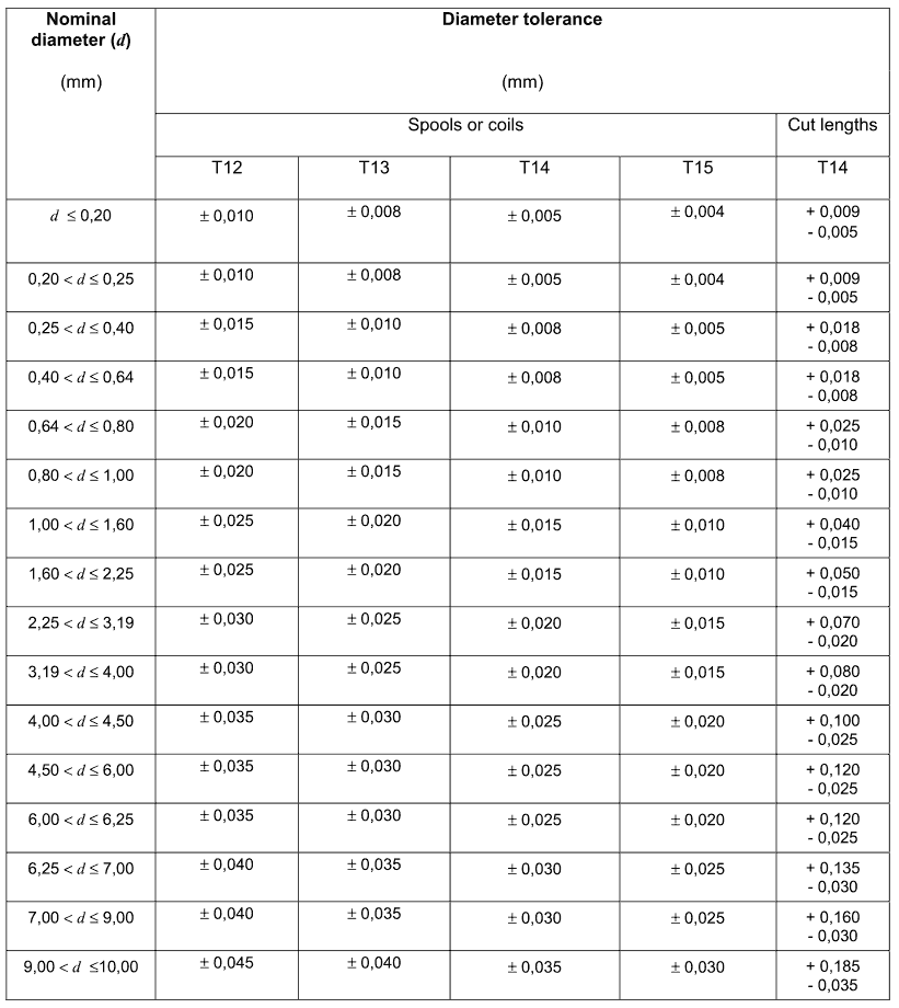
4.10.1 Tolerances on diameter
The tolerances on diameter are given in Table 5:
Table 5- Diameter tolerances
4.10.2 Out of roundness
The out of roundness, i.e. the difference between the maximum and minimum diameter of the wire in the same cross section of the wire, shall not be more than 50 % of the total permissible deviation for wire in coils, specified in Table 5. For special applications tighter tolerances may be agreed at the time of enquiry and order.
4.10.3 Tolerance on the length of straightened and cut lengths
The requirements for length tolerance and straightness are as in EN 10218-2. The tolerance on the length shall only be on the positive keeping the same tolerance range (see Table 6).
Table 6- Tolerance on the length of straightened and cut wire

5 Testing and inspection
5.1 Inspection and inspection documents
Products conforming with this standard shall be delivered with specific testing (see EN 10021) and the relevant inspection document (see EN 10204) agreed at the time of enquiry and order.
The inspection document shall include the following information:
-the document number;
-the date of issue;
-the customer’s order number and name;
-the confirmation that the material complies with the requirements of the order;
-the tests, the results and where appropriate presented in a statistical manner;
-the identification by production lot number and heat number;
-the heat analysis;
-results of optional tests agreed.
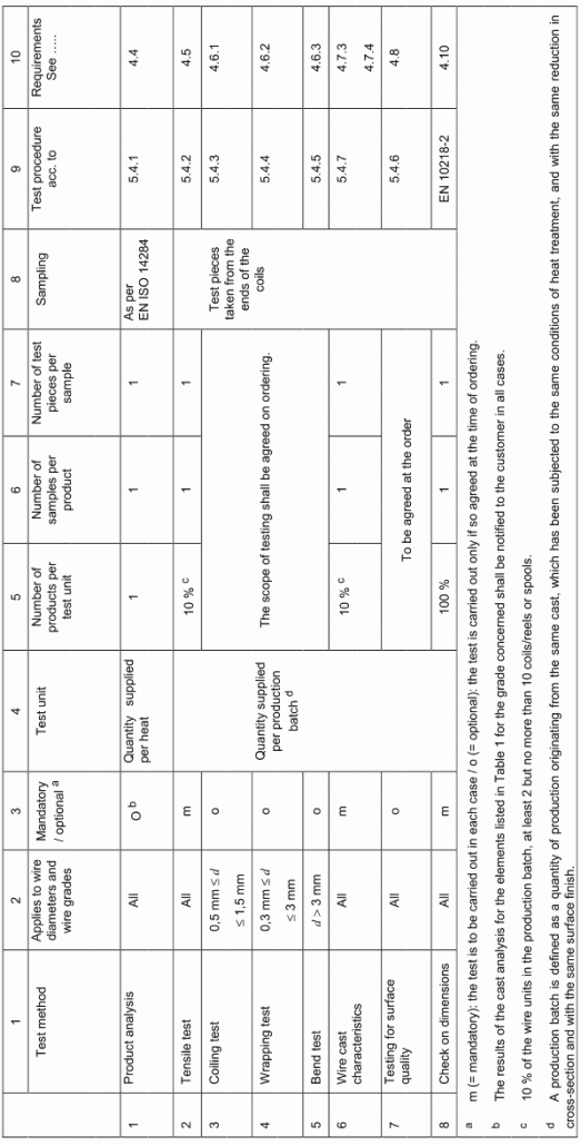
5.2 Extent of testing for specific testing
The extent of testing shall be in accordance with Table 7.
Table 7 Extent of testing and sampling for specific testing and summary of the information on test procedure and requirements
5.3 Sampling
Sampling and testing preparation shall be in accordance with EN ISO 377 and EN ISO 14284.
Samples shall be taken at the end of the coils, reels or spools or at random for wire in the form of straightened and cut lengths. Table 7/column 8 gives further details.
5.4 Test methods
5.4.1 Chemical composition
Unless otherwise agreed at the time of ordering the choice of a suitable physical or chemical method of analysis for the determination of product analysis shall be at the discretion of the supplier.
In cases of dispute the analysis shall be carried out by a laboratory approved by the two parties. The method of analysis to be applied shall be agreed upon, where possible in accordance with CEN/TR 10261.
5.4.2 Tensile test
The tensile test shall be carried out according to EN ISO 6892-1, on samples with the full cross section of the wire. For the calculation of the tensile strength the actual cross-section based on the actual wire diameter is applied.
5.4.3 Coiling test
The coiling test shall be carried out in the following manner: A test piece – approximately 500 mm in length shall be closely wound, under slight but reasonably uniform tension on a mandrel three to three and a half times the nominal diameter. The mandrel diameter shall however be at least 1,00 mm. The close coil shall be stretched so that after releasing the tress it sets to approx. three times its original length.
The surface condition of the wire and the regularity of the spring pitch and individual windings shall be inspected with the test piece in this condition.
5.4.4 Wrapping test
The wrapping test for ductility shall be carried out according to EN 10218-1. The wire shall be wrapped 8 turns around a mandrel with a diameter equal to the wire diameter.
5.4.5 Simple bend test
For the bend test a wire sample of sufficient length shall be bent in U form around a mandrel with a diameter equal to twice the wire diameter for sizes above 3,00 mm to 6,50 mm and equal to three times the wire diameter for sizes above 6, 50 mm. For practical reasons the wire shall be deemed to have met the requirements of this standard if it withstands bending around a mandrel smaller than the one specified.
In carrying out the test the wire shall be free to move longitudinally in the forming device.
5.4.6 Reverse torsion test
The torsion test shall be carried out according to EN 10218-1 with the specific requirement that the wire is twisted first 2 complete turns in one direction and then 2 turns back in the other direction without revealing surface cracks visible to the naked eye.
The distance between the clamps shall be 100 d with a maximum of 300 mm.
5.4.7 The wire cast
The circular and helix cast as defined in EN 10218-1 shall be tested on a sufficiently long piece of wire so as to form a full free wap (single convolution of wire) ensuring that it is not bent or mechanically damaged.
5.5 Retests
Retests shall be carried out according to EN 10021.
6 Marking and packaging
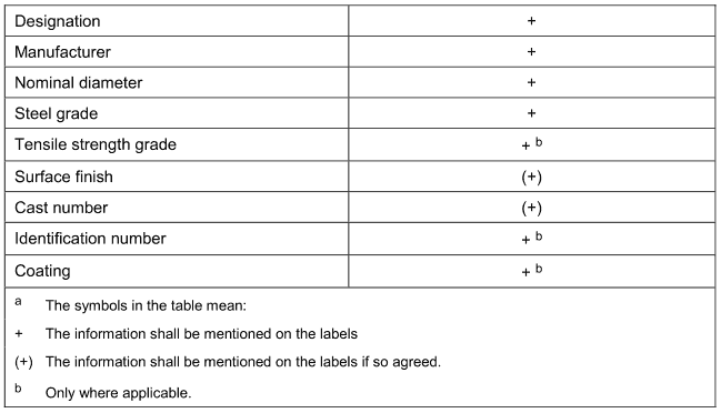
Each unit shall be properly marked and identified so as to permit identification, traceability and reference to the inspection documents. The labels shall withstand normal handling and show the information according to Table 8. Other information shall be subject of an agreement between the parties.
Wire shipments shall be suitably protected against mechanical damage and/or contamination during transport.
Table 8 – information on the labelsa
